Paul Committee Report
PAUL COMMITTEE REPORT
In order to help the mining industry in drawing up support plans properly and scientifically the Director General of Mines Safety constituted an Expert Group in December 1988 under the chairmanship of Shri K. Paul, Dy. D.G.M.S. The Expert Group made a detailed study of the roof fall and side fall accidents, mechanism of failures, support practices in use in different coalfields in India and abroad and the different systems of rock mass classification. On the basis of these studies the group finalized the “Guidelines for drawing up support plans in bord and pillar workings in coal mines” and submitted its report in May 1990. This report, popularly called the Paul Committee Report, was sent to all the coal companies in October 1990 for implementation.
Some of the findings of this Expert Group and its recommendations are given below: –
Findings from an analysis of a large number of roof-fall and side-fall accidents:
- About 45% of the accidents took place in freshly exposed roof areas.
- In 80% of the cases, the thickness of fall was less than 50 cm.
- More falls occurred in coal/shale roof rocks. In sandstone roofs, the main cause of fall was geological disturbance.
- Over 70% of the mines were dry. Only in a few mines, heavy, seepage of water was attributed as the cause of roof deterioration.
- Where the falls took place, either no supports were provided or the supports provided were inadequate or were installed improperly. Conventional timber supports were found to be inadequate in a majority of the cases. There was only one case where roof-stitching had failed and two cases where bolting had failed due to poor grouting.
- Of the 118 accidents that were analyzed, two were due to fall of side, three were due to air-blast and two occurred while withdrawing supports.
- Weak bedding planes (delamination) were the primary causative factor for poor roofs. Geological discontinuities such as joints, slips, and faults ranked second in order of importance. Weathering of shales in contact with water or in humid mine atmosphere was also responsible for deteriorating roof conditions in some cases.
Recommendations of the Expert Group (Paul Committee)
-
Geomechanics classifications
Engineering classification approach being the only accepted way of qualitative and semi-quantitative assessment of the roof conditions, this method should be adopted in all the mines. The geo-mechanical classification developed by CMRS-ISM is applicable to Indian ground conditions. Any support plan should first indicate the class of roof and the rock mass rating obtained from this approach.
-
Support systems
The Expert Group recommends that, in general, extended use of roof bolting as a method of support would have to become an integral part of future mining systems. This can not only be installed early to support the green roof but also, as an active support, has a distinctive edge vis-à-vis passive supports currently in use in coal mines. Full column grouted bolts using quick-setting cement capsules appear ideal for most of the conditions prevailing in Indian mines. The recommendations for the support system, both for bolting and alternative support-systems in different geo-mining situations are given in tables 4 and 5. The support plan should be based on these guidelines. In mining under shallow cover, however extra care and caution need to be exercised for application of roof bolting.
While timber supports as per the Systematic Support Rules will continue to be used in conventional depillaring panels, the split galleries could be supported with roof bolts or rope dowels. Pit props and steel props will also find application in depillaring panels as replacement of timber props. Light duty hydraulic props should be useful in depillaring areas where the extraction height is less than 3.5 m. For greater height of extraction, steel square chocks with wooden sleepers can be used. In mechanized depillaring panels using LHDs and SDLs, the original and split galleries should be supported with roof bolts. The slices may also be supported with roof bolts and channels/W-straps, if necessary, except in such roofs where the potential of air-blast exists.
In thick coal seams, if extraction is proposed using multiple slices in ascending order, use of cable bolts should be undertaken while working the bottom slice. Span of galleries plays a very important part in the stability of the roof. In the case of bad roofs, it is recommended that, apart from supporting the roof, the span should be minimized and formation of four-way junctions avoided, where feasible. Until such time as these recommendations are implemented and some experience gained, roof bolting should not be the sole means of support in roadways which are more than 5 m in width. In seams liable to spalling from sides, bolting with or without side straps and stitching the sides should be the prime means of rib control.
-
Specifications for bolting systems
All components of the roof bolt assembly should comply with the BIS specifications, wherever available. Generally speaking, the length of the bolt should be at least one-third of the width of the roadway. However, the length should normally be not less than 1.5 m. For restricted height, coupled bolts would have to be used. A 20-22 mm diameter bolt (ribbed bar) will meet the requirements in most of the cases. The bolting density for the three types of roof, where bolting has been recommended, will be as given below:
- Poor: 1.2 to 1.5 bolts/sq.m.
- Fair: 1.0 bolt/sq.m.
- Good: 0.7 bolt/sq;m.
At junctions, the density should be increased by 25%. The bearing plates should be not less than 15 cm x 15 cm or equivalent area. The bolt angle should generally be normal to the bedding plane in rectangular roadways. The rib side bolts may in certain cases be inclined outwards.
-
Requirements for drilling of holes
To be effective, the drilling of roof holes for bolting has to be mechanized using hydraulic or compressed air operated drilling machines.
In case of high strength abrasive roof rocks, such as massive sandstone, high torque compressed air operated drill machines should be used. Survey of indigenous drilling systems makes it evident that in not-so-hard and abrasive conditions, existing drilling systems may suffice. However, for drilling conditions which are intractable, import of drilling systems for bolting should be liberalized until such time as indigenous development of the systems can be done.
While wet drilling of the holes in stone is mandatory, for bolting this is additionally required to clear all the dust and ensure maximum bond strength between the strata and the bond material. This is equally applicable in the case of coal.
-
Monitoring of support performance
With conventional free-standing supports there are clear indications when they carry excessive load. Roof bolts, however, give no visual indication of load increase and therefore no indication of how close either the individual bolt or the system is to ultimate failure. Failure of bolted roof can be more rapid and more extensive and with less warning than the failures experienced with conventional supports.
Systematic monitoring of roof bolted systems will therefore, be essential to assess the stability of the system and provide feedback which will allow future designs to be fine-tuned. Monitoring can be divided into broad categories, namely,
-
Measurement of bolt performance:
This is ascertained by anchorage capacity test (pull testing) conducted on about 10% of the bolts installed. A minimum of 5 tonnes anchorage strength should be achieved.
-
Measurement of strata behaviour:
The stability of the roadway should be monitored using sag indicators, sag bolts, bolt load-cells, convergence recorders, etc. For this purpose there should be a systematic plan of establishing monitoring stations both in active areas and in the permanent roadways outbye. Borehole extensometers for measuring strata dilation at different points along the roof may also be used where appropriate.
It is desirable that a combination of monitoring techniques be used in order to provide meaningful result and differentiate between difficult loading conditions.
-
Training needs
Roof bolting is a new concept to the workforce. It is therefore extremely important to make the workforce aware of the principles of bolting, the objectives and above all, to give them confidence in the new system of roof support. For these reasons, both surface and underground training sessions are to be carried out.
-
Implementation strategy
There should be a skilled group (roof bolting task force at the Area level, to check/guide installation work and monitor performance, to oversee the Area level work there should be a group of specialists at the corporate level.
For standardization and implementation of roof bolting strategy, the coal industry should sponsor a Study Group/Expert Group to examine the status of roof bolting and the infrastructure for roof bolting available in the USA and Australia, both in room and pillar and longwall mining systems.
Using the feedback from the Study Group and based on experiences of implementation of these recommendations, an Expert Group should within the next three years, review the status of roof bolting and formalize prescriptive guidelines for use by the industry.
-
General:
Recommendations as above are essentially guidelines and need to be tempered with engineering judgment.
In making the above recommendations the Expert Group has taken due note of one of the observations of the Royal Commission on the Health and Safety of Workers in Mines, Canada (1976) that “there is no attainable state of absolute health and safety. There are levels of risks accepted or tolerated to a degree by the parties concerned”. Mines can only exist where economically viable operations can be conducted. Within operating mines, the acceptable levels of occupational risks are determined by (1) the quality and kind of industrial management and supervision; (2) the degree of participation and commitment from employees, individually and collectively, in labour union and otherwise; (3) the state of social expectations and concerns in mining communities and in the public at large; (4) the measure of political attention as expressed in legislation, in the related governmental administrative practices for monitoring compliance, and in the provision of compensation; and (5) the combined effectiveness of the above parties in operating as a system.
Cognizant of the above philosophy on levels of acceptable risks, the Expert Group is convinced that roof bolting has much to offer as a fast and reliable primary support system for coal mining industry, which can usher in a new era of technical change.
-
Future R & D
Future R & D should focus inter-alia on the following:
- The suitability of different bolting systems under different roof conditions.
- Monitoring of roof convergence and other parameters to check the efficacy of the roof bolting system, including the effect on fall in the goaf after extraction in conjunction with roof bolting.
- The suitability of different drilling machines under Indian roof rock conditions.
- The adaptability and availability of smaller diameter drill rods, bits and bolts.
- The safe width of galleries under supported and unsupported conditions for different classes of roof.
- Development of a simpler rock mass classification so that a manager in the field can be aided to classify rock mass in his colliery without outside help and without sacrificing much accuracy.
- The design and development of material of the shell for retractable bolts.
GUIDELINES FOR DRAWING UP SUPOPRT PLANS IN BORD & PILLAR WORKING IN COAL MINES
General
The various stages of designing a suitable roof support system and ensuring a successful installation are basically as follows:
- A geotechnical survey and interpretation of the survey findings;
- Selection/designing of a support system based on the above interpretation;
- Selection of equipment;
- Actual installation process; and
- Monitoring of the system.
Among the several rock mass classification systems in vogue, two systems are particularly used to characterize mining ground conditions.
Barton’s Q-System
The first one is Q-system or Rock Quality Index developed by Barton, Lien and Lunde of Norwegian Geotechnical Institute. The rock mass quality is evaluated as:
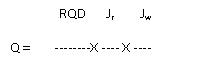
Where RQD is the rock quality designation (or percent core recovery of rock pieces of 10 cm or more in length), size of hole being NX.
Jn is joint set number,
Jr is joint roughness number,
Ja is joint alteration number,
Jw is joint water reduction factor, and
SRF is stress reduction factor.
Based on the value of Q, the rock mass can be described as “exceptionally good” (Q = 400 to 1000) to “exceptionally poor” (Q = 0.001 to 0.01). Using the Q value, the maximum unsupported span of a roof can be estimated by the formula:
Span (in m ) = 2 X ESR X (Q)0.4
Where ESR is excavation support ratio (which is 3 to 5 for temporary mine workings and 1.6 for permanent workings). The rock load (Proof) can also be estimated from the empirical formula:
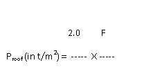
Where F = 1 if Jr is 9 or more,
Or F = ((Jr)1/2)/3 if Jr is less than 9.
Further, depending on the different values of the parameters and Q, 38 support categories have been identified.
Bieniawski’s RMR system
The second classification system is Bieniawski’s Geomechanics Classification or RMR (rock mass rating) approach initially developed for tunnels in South Africa, but later extended to mine workings in the USA. There are five parameters in this classification:
- Intact rock strength,
- Rock quality designation (RQD),
- Joint spacing,
- Condition of joints (roughness, aperture & weathering), and
- Groundwater seepage.
Rating division for each of the parameters is given, and the rock mass rating, RMR, is the sum of the five individual ratings. Based on RMR, the roof is classified as “very good” (RMR = 80 to 100) to “very poor” (RMR = 0 to 20). Theoretical relation for estimation of rock load is derived and a support guide is also provided.
Suitability of Q-System/RMR System
These two classification systems have been applied to about thirty Indian coal mining cases. The Q classification is suitable for highly jointed rocks, and particularly for hard rock conditions. Most of the parameters in this system are based on joint attributes whereas stability in coal mines is not merely joint-controlled. The stress reduction factor also has no relation with the stress field occurring around multiple openings like coal mine roadways. The parameter descriptions in Q system leave much to subjective judgment.
The RMR system gives results nearer to the actual roof conditions, but only in good and very good roof conditions. It was recognized that in most of the Indian coal mines, bedding planes, structural features and weathering of roof rocks, are the major causes of roof failure. But in Bieniawski’s approach, consideration is not given to sedimentary features, structural features other than joints, and to weatherability of rocks. Deviations in the results also arise from the weightages for the parameters, which need to be adjusted to the Indian rock conditions.
In view of the limitations of the above two system, the CMRS/ISM Geomechanics Classification has been developed. This is a practical rock mass classification system, specifically suitable for bord and pillar development roadways.
CMRS/ISM Geomechanics Classification
This rock mass classification system is being regularly used by various institutes. The five parameters in this classification and their importance ratings are :
| |
Max. rating |
| Layering |
30 |
| Structural features |
25 |
| Rock weatherability |
20 |
| Strength of the roof rock |
15 |
| Ground water seepage |
10 |
The parameter values for the classification should be determined individually for all the rock types in the roof, up to a height of at least 2m.
-
Layering
Spacing between the bedding planes or planes of discontinuities should be measured using borehole staratascope in a 2.0 m long drill hole made in the roof. Alternately, all bedding planes or fissile (weak) planes within the roof strata can be measured in any roof exposure like a roof fall area, shaft section or cross measure drift. Core drilling should be attempted wherever feasible, and the core log can be used to evaluate RQD and layer thickness. Average of five values should be taken and layer thickness should be expressed in cm.
Structural features
Random geological mapping should be carried out, and all the geological features (discontinuities, like joints, faults and slips, and sedimentary features like cross bedding, sandstone channels) should be carefully recorded. The relative orientation, spacing and degree of abundance for all these features should be noted. Their influence on gallery stability should be assessed, and the structural index for each feature should be determined from Table 1.
Table 1: Indices for parameter structural features
| Presence of major faults |
|
| |
net displacement > 10 m |
15 |
| |
displacement 2 – 10 m |
8 |
| |
displacement < 2m |
5 |
| Presence of minor faults/slips |
|
| |
spacing < 5 m |
|
| |
orientation unfavourable |
10 |
| |
orientation not unfavourable |
5 |
| |
spacing > 5 m |
|
| |
orientation unfavourable |
7 |
| |
orientation not unfavourable |
3 |
| Occurrence of joints and cleats |
|
| |
|
Orientation unfavourable |
Orientation
not unfavourable
|
| |
a) Minimum spacing <30 cm |
|
|
| |
single set |
6 |
4 |
| |
two sets |
7 |
6 |
| |
more than two sets |
8
|
8 |
| |
b) Minimum spacing > 30 cm |
|
|
| |
single set |
5 |
2 |
| |
two sets |
6 |
4 |
| |
more than two sets |
6 |
6 |
| Sedimentary features |
|
|
| |
lateral thickness variations |
3 |
| |
sandstone channels |
6 |
| |
kettlebottoms |
4 |
| |
plant impressions |
3 |
| |
ball coal |
4 |
| Index for ‘structural features’ = sum of indices for individual features. |
-
Weatherability
ISRM standard slake durability test should be conducted on fresh, samples of roof rock collected from the mine to determine the susceptibility of rocks to weathering failure on contact with water or the atmospheric moisture. For this test, weigh exactly any ten irregular pieces of the sample (the total weight should be between 450 and 500 g); place them in the test drum immersed in water, and rotate it for 10 minutes at 20 rmp; dry the material retained in the drum and weigh it again. Weight percentage of material remaining after the test is the first cycle slake durability index, expressed in percentage. Mean of three such first cycle values should be taken. Core may be broken to obtain the samples.
-
Rock strength
Point load test is the standard index test for measuring the strength of rocks in the field. Irregular samples having a ratio of 2: 1 for longer axis to shorter axis can be used for the test. The sample is kept between the pointed platens, and the load is applied gently but steadily. The load at failure (in kg) divided by the square of the distance between the platens (in cm) gives the point load index (Is). The mean of the highest five values out of at least 10 sample tests should be taken. The compressive strength of the rocks can be obtained from the irregular lump point load index for Indian coal measure rocks by the relation:
Co = 14 x Is (in kg/cm2)
-
Ground water
A 2 m long vertical hole should be drilled in the immediate roof and the water seeping through the hole after half an hour should be collected in a measuring cylinder. The average of three values from three different holes should be taken and expressed in ml per minute.
The ratings for the five parameters are given in Table 1. Rock Mass Rating (RMR) is the sum of the five parameter ratings. If there are more than one rock type in the roof, RMR is evaluated separately for each rock type, and the combined RMR is obtained as:
Combined RMR = S (RMR of each bed X bed thickness)/S (thickness of each bed)
The RMR so obtained may be adjusted, if necessary, to account for some special situations in the mine like great depth, stresses and method of work. Figure 1 shows the flow chart for deriving the rock mass rating while Table 3 gives the value of adjustment factors.
Table 2: Classification ratings for parameters
| Parameter |
Range of values |
| 1. Layer thickness |
(cm)
Rating |
<2.5
0-5 |
2.5-7.5
6-12 |
7.5 – 20
13-20 |
20- 50
21 -26 |
>50
27-30 |
| 2. Structural features |
(index)
Rating |
> 14
0-4 |
14-11
5- 10 |
11-7
11-16 |
7-4
17-21 |
4-10
22-25 |
| 3. Weatherability |
(%)
Rating |
<60
0-3 |
60-80
4-8 |
85 – 97
9-13 |
97-99
14- 17 |
>9Q
18-20 |
| 4. Strength of the rock |
(kg/sq.cm)
Rating |
< 100
0- 1 |
100-300
3-6 |
300-600
7-10 |
600 – 900
11-13 |
>900
14- 15 |
| 5. Ground water seepage rate |
(ml/m in)
Rating |
>2000
0- 1 |
2000-200
2-4 |
200-20
5-7 |
20-0
8-9 |
Dry
10 |
| RMR |
|
0-20 |
20 – 40 |
40-60 |
60-80 |
80-100 |
| CLASS |
|
V |
IV |
III |
II |
1 |
| DESCRIPTION |
|
VERY POOR |
POOR |
FAIR |
GOOD |
VERY GOOD |
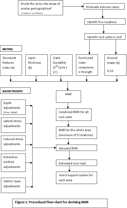
Table 3: Adjustment Factors for RMR
| |
Adjustment to RMR |
Adjusted RMR |
| 1. Depth |
|
|
| Less than 250 m |
Nil |
RMR x 1.0 |
| 250-400m |
10% reduction |
RMR x 0.9 |
| 400- 600 m |
20% reduction |
RMR x 0.8 |
| More than 600 m |
30% reduction |
RMR x 0.7 |
| 2. Lateral stress |
|
|
| Assumed stress amount |
|
|
| Small |
10% reduction |
RMR x 0.9 |
| Moderate |
20% reduction |
RMR x 0.8 |
| High |
30% reduction |
RMR x 0.7 |
| 3. Induced stresses |
|
|
| Stress situation : |
|
|
| No adjacent working in the same seam |
Nil |
RMR x
1 .0 |
| Extraction area within 20-40 m in the same seam |
!0% reduction |
RMR x 0.9 |
| Extraction areas within 10-20 m in the same scam |
Upto 30% reduction |
RMR x (0.7 to 0.8) |
| Working above with 1 0-20 m parting |
10% reduction |
RMR x 0.9 |
| Working above with 3 -10 m parting |
Upto 30% reduction |
RMR x {0.9 to 0.8) |
| 4. Method of excavation |
|
|
| Continuous miner |
10% increase |
RMR x 1.1 |
| Undercut and blasting |
Nil |
RMR x 1.0 |
| Blasting off -the-solid |
10% reduction |
RMR x 0.9 |
| 5. Gallery span |
|
|
| Less than 4.5 m |
Nil |
RMR x 1.0 |
| 4.5-6.0 m |
1 0 – 20% reduction |
RMR x (0.8 to 0.9) |
The final RMR for the roof is classified as :
| RMR |
Roof Class |
Rood Description |
| 0-20 |
V |
Very poor |
| 20-40 |
IV |
Poor |
| 40-60 |
III |
Fair |
| 60-80 |
II |
Good |
| 80-100 |
I |
Very good |
An empirical relation obtained between RMR and rock loads is:
Likely rock load in tonnes/m2 = span in m X mean rock density x (1.7 -0.037 RMR +0.0002 RMR2)
In the USA, Unal related rock load to RMR by the following expression:
P = VB (100 -RMR) /100
Where
P = rock load in t/m2
B = width of gallery in m
V = density of rock in t/m3
Example for Application of the Classification
At Satgram Incline (Satgram Area), ECL, the immediate roof of Dishergarh seam is 0 to 15 cm thick carbonaceous shale, overlain by 0.6 to 0.7 m thick layered silty sandstone. The carbonaceous shale is being dressed down in some places or it is totally absent. The roof is uneven, and has innumerable plant impressions. Two sets of joints are mapped, the prominent one having a trend 35° -215°, and the other at right angles to it. The former set is a open joint set (aperture 2 mm) and is more or less parallel to the dip-rise galleries. The galleries are 3.2 m, and at some places 3.6 m. in width.
Point load index of the silty sandstone is 22.65 (irregular lump test) or compressive strength is 317 kg/cm2. Dry density of the rock is 2.215 t/m3. The RMR for this layer of silty sandstone is calculated as below:
| Parameter |
Value |
Rating |
| Layer thickness |
6cm |
11 |
| Structural index (two joint sets) |
6 |
17 |
| Weatherability (1 cycle slaking index) |
89.7% |
10 |
| Rock strength |
317 kg/cm2 |
7 |
| Groundwater seepage |
-dry- |
10 |
| |
RMR 55 |
|
The RMR for other layers of rock upto 2 m are to be calculated in the same manner. Assuming a combined RMR of 55 for this roof –
Expected rock load
= rock density X gallery width X (1.7 -0.037 X RMR + 0.0002 X RMR2)
=2.215 X3.2 X (1.7-0.037 X 55 +0.0002 X 55 X 55)
=1.9 t/m2
For 3.6 m, wide galleries, the likely rock load is 2.15 t/sq.m. The support recommended for this roof is roof bolting using full column cement grouts, with three bolts in a row for 3.2 m wide galleries and four bolts in a row for 3.6 m galleries, at 1.2 m row interval. With this support system, the support resistance provided would be :
(no. of bolts x bearing strength of a bolt) / (row spacing x gallery width)
(3 x 6) / (1.2 x 3.2) = 4.7 t/m2
Therefore, the safety factor = support load/likely rock load = 4.7/ 1.9 = 2.5
In case of 3.6 m wide galleries, the support load would be:
(4 x 6) / (1.2 x 3.6) = 5.6 t/m2
And the safety factor in this case = 5.6 / 2.15 = 2.6
Pre-Mining Assessment of Roof Quality
The Geo-mechanics classification can be applied even at the exploratory stage of a mine. Most of the parameters can be obtained by core drilling from the surface. The core pieces of the immediate roof of a seam can be measured to determine RQD and layer thickness. Dry density, strength and weatherability properties can be obtained by laboratory testing of the cores. Pumping tests above the seam level would indicate the groundwater character of the roof strata. Most of the structural features like jointing and major faults, and many sedimentary features could be identified by a set of two or more drill holes. From this information, a rough assessment of the support requirement could be made prior to mining. This should be updated after making exploratory drivages and while actual mining. In case there are other working mines in the area, information can be obtained and used to plan initially which may need to be updated depending on the experience.
Table 4: Recommended support system for development workings
| Roof description (class) |
Boiling systems |
Conventional supports |
| 1. Very Poor Roof
(Class V)
|
|
(a) Yielding steel arches under high stress conditions, (b) Rigid steel arches under moderate stress conditions. |
| 2. Poor Roof
(Class IV)
|
(a) Full column grouted bolls using quick setting grout, supplemented with steel channel/w-strap. For flaky roof, wire mesh in addition. (b) For temporary roadways, roof stitching along with roof bolls and W-straps. |
(a) Rigid steel arches for roof with structural disturbances, (b) Steel beam (200 mm x 100 mm) set on brick wall for permanent roadways
(c) Steel bars set into pillars or on steel props.
|
| 3. Fair Roof
(Class III)
|
(a) Full column grouted bolts using quick selling grout, (b) For temporary roadways, roof stitching supplemented by spot bolting in disturbed areas. |
(a) Steel cross bars set into pillars or on steel props for permanent roadways. (b) Steel props for temporary roadways. Can also be used in permanent roadways. |
| 4. Good Roof
(Class II)
|
(a) Full column grouted bolts for permanent roadways, (b) Roof stitching with additional spot bolting in disturbed areas in permanent roadways. |
Steel props for permanent roadways. |
| 5. Very Good Roof
(Class I)
|
No support except for spot bolting in disturbed areas. |
N.B.:
- Grouted bolts also imply the use of cement capsules.
- ‘Quick setting’ implies the development of an anchorage capacity of al least 10 kN in 30 minutes and about 50 kN in 2 hours.
Table 5: Recommended support system for freshly exposed roof (upto 10 m from the face)
| Roof description (class) |
Bolting systems |
Conventional supports |
| 1. Very Poor Roof (Class V} |
|
The system of support indicated in Table 4 should be erected closely following the face, |
| 2. Poor Roof (Class IV) |
(a) Point anchored (mechanical or grouted with quick setting resin) bolts for immediate tension, to be fully grouted soon afterwards, W- straps where necessary.(b) Full column grouted bolts with quick setting grout. |
(a) Cross bars on steel chocks or hydraulic props with minimum 5 tonnes setting load. |
| 3. Fair Roof (Class III) |
(a) Combination bolts as at (a) above.(b) Full column grouted bolts with quick setting grout.
(c) Recoverable, bolls.
|
(a) Light duly hydraulic props.(b) Steel props.
(c) Triangular chocks at junctions.
(d) Safari supports.
|
| 4. Good Roof (Class II) |
(a) Recoverable bolts.(b) Full column grouted -bolts |
(a) Steel props. (b) Safari supports. |
| 5. Very Good Roof (Class 1) |
No support except for spot bolting in disturbed areas. |
N.B.:
- Grouted bolts also imply the use of cement capsules,
- ‘Quick setting’ implies the development of an anchorage capacity of at least 10 kN in 30 minutes and about 50 kN in 2 hours.
- Vertical supports should be set with minimum 5 tonnes setting load to prevent dislodgement due to blasting.
- ‘Very poor’ and ‘poor’ roof should be supported as soon as it has been exposed.